Background
Alternating current (AC) is current which flows back and forth along a conductor. (In contrast, direct current (DC) is current which flows in one direction only.) Alternating current is the result of an alternating voltage (force) pushing electric charges back and forth.
The diagram to the right shows an AC generator capable of producing an alternating voltage. It is basically a loop of wire rotating between the poles of a magnet. The diagram also shows a graph of the voltage v produced by the generator as a function of time t as the loop L rotates through one complete circle. This curve is called a sinusoidal waveform. It has the formula:
where
- v is the voltage,
- t is the time,
- sin is the function that gives the curve its wave shape,
and A, ω and φ are parameters that describe the details of the curve:
- A is called the amplitude and is the maximum height that the curve reaches,
- ω is called the angular velocity and describes how rapidly the curve oscillates (it is actually the rate of rotation of the generator measured in radians per second), and
- φ is called the phase angle. It determines the shift of the wave left or right. A shift of 360 degrees (or 2π radians) is a shift of one complete cycle and any smaller shift is a shift of less than one cycle.
When v is positive (at the top or crest of the wave) this means that the upper terminal has a greater voltage than the lower terminal. And when v is negative then the lower terminal has a greater voltage than the upper terminal. An oscilloscope is capable of displaying such waveforms.
If a circuit is connected to the terminals then the resulting current will alternate in direction as well, flowing first one way through the circuit, then reversing itself and flowing the opposite way. AC has several important advantages over DC. Among them are ease of generation, efficiency of transmission and safety of use.
Problem

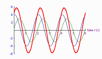
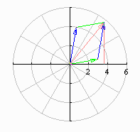
An important problem is that of calculating the combined voltage produced by a pair of generators connected in series. The diagram to the right shows a green curve, a blue curve and a red curve. The green curve describes the voltage produced by one generator and the blue curve describes the voltage produced by a second generator. The equations for these curves are known to be:

The red curve describes the voltage produced when the two generators are connected in series. It is simply the sum of the heights of the green and blue voltage curves. The problem:
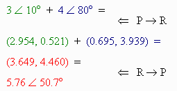
Find the equation of the red voltage curve.


