Background
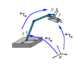
In many robotics problems it is useful to define more than one coordinate system. For example in the picture to the right we have defined three coordinate systems. We have attached a coordinate system called B to the robot’s base, another coordinate system called H to its hand and another called P to the piece that the robot must grasp. (By attached we mean that if we move the base, the hand or the piece then the corresponding coordinate system moves with it.) Coordinate system P is useful for locating points on the cylinder. Coordinate system B is useful for describing the location of the hand. And coordinate system H is useful for measuring distances from the hand.
Often we know the position and orientation of the piece P relative to the robot’s base B but we need to know it relative to the hand H so that the hand can be moved correctly to pick up the piece. This can be computed if we know the position and orientation of the hand relative to the base. Note that orientation as well as position is important if we want the hand to be properly oriented to grasp the piece.
In this background section we will explain how a transformation matrix can be used to describe the location and orientation of a second coordinate system with respect to a first coordinate system.
Consider the following transformation matrix
T = 
Here is how this transformation matrix can be used to describe the location and orientation of a second coordinate system relative to a first coordinate system. We apply the transformation matrix to the origin and the endpoints of the unit vectors of the first coordinate system. This matrix multiplication produces the origin and the endpoints of the unit vectors of the second coordinate system:
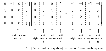
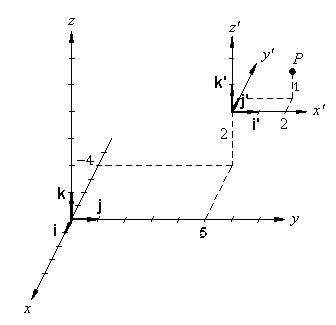
These two coordinate systems are shown in the picture to the right. (The second coordinate system is the one with the tick marks.) Points can be located relative to either coordinate system. For example the point P is located at (x’ = 2, y’ = 1, z’ = 1) in the second coordinate system and at (x = -5, y = 7, z = 3) in the first coordinate system.
Probably the quickest way to "design" a transformation matrix like
T = 
is to notice that the three columns of the 3x3 submatrix give the orientation of the second coordinate system in terms of the first like this:

and that the three element vector
from the last column gives the position of the origin of the second coordinate system in terms of the origin of the first.
Problem
A robot’s hand is supposed to pick up a part. A coordinate system, P, attached to the part is located relative to the "world" coordinate system, W, by the transformation matrix
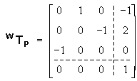
and the robot’s base frame, B, is located relative to the world frame by
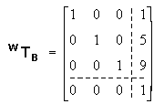
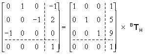
In order to put the hand on the part, we wish to align the hand frame, H and the part frame. What is the transformation matrix
(giving the hand frame relative to the robot base frame) that makes this happen?
