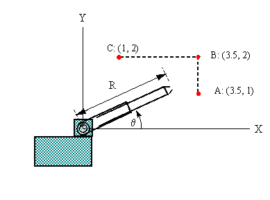
The diagram shows a robot with a telescoping arm.
Note the two basic variables:
θ= angular inclination of the arm (rads)
R = length of the arm (meters)
Each of these variables can be controlled separately.
In any practical situation, the manipulator (the component at the end of the arm) has to move in a prescribed way. Suppose that the angle θ can be increased or decreased, in response to commands from a computer. While this is happening, the arm can also be extended or retracted. We want to obtain a mathematical description of how R should be adjusted, in relation to θ, so that the manipulator will trace out a particular path.
(Note that the control of an actual robot is a much more complicated affair. For example, movements have to be graduated, because of inertia, and in order to prevent excessive strain on mechanical linkages. Robots are programmed to move according to complex dynamical equations that take into account velocity, acceleration, and mass distributions.)
The Problem
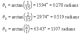
In the above diagram, the points A, B, and C lie in one vertical plane. Suppose that the manipulator of the robot has to make the following repetitive movements: from point A to point B to point C, then back to A via the shortest (diagonal) route. Find the formulas (in terms of R and θ) that will be needed in programming these movements.
Theory
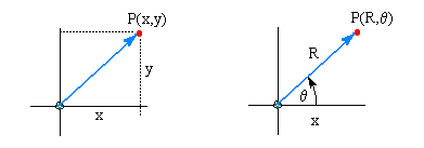
The familiar Cartesian, or x-y coordinate system is not the only way of describing the location of points in space. Some physical problems become easier when formulated in terms of a coordinate system that matches the inherent geometry of the problem. Our problem is essentially rotational, and the polar coordinate system is particularly suited to such a configuration.
In the diagrams above we see the point P described in two different ways: first in terms of the usual displacements x and y, and again in terms of the two rotational variables R and θ.
Suppose that x = y = 1.
Then the point can be given in rectangular (Cartesian) form:
(x,y) = (1,1)
Or it can be given in polar form:
Applying right-angle trigonometry, we can obtain these conversion formulas:
x = R cos( θ) and y = R sin(θ)
In either system, it is possible to express a relation between the two variables.
In the Cartesian system, we write functions in the form y(x), where y depends on x:
for example, y(x) = 3x + 10
In the polar system, we write functions in the form R(θ), where R depends on θ:
for example, R(θ) = 3θ + 10
In both systems we obtain points in the same way: we assign progressive values to the independent variable ( x or θ) and use the equation to determine the corresponding value of the dependent variable (y or R). Thus we obtain a set of points which can be plotted. The two functions shown above look the same, but they describe quite different curves. In the Cartesian system we get a straight line, in the polar system we get a spiral.
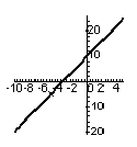
y = 3x + 10
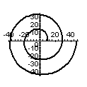
R = 3θ + 10
