Electric Circuit Symbols and Terminology
Here is an electric circuit diagram:
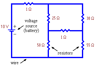
Notice these symbols:
- The
 symbol for a voltage source (this could be for example a battery). Voltage sources generate a force or "pressure" which causes electric
currents to flow in the circuit. The voltage source shown is
rated at 10 volts (abbreviation V). This means that the voltage
or "pressure" is 10 volts higher at the + or
wide-line side of the battery than at the - or narrow-line side
of the battery. As a result, electric charges are given a force
in the upward direction (from the - side to the + side).
- The
 symbol for a resistor. Resistors are devices that impede the flow of electric current. The resistor at the lower right has a resistance of 55 ohms (abbrev Ω).
- The
 symbol for a wire. A wire is
assumed to have no resistance.
Principal Nodes or Junctions and Branches
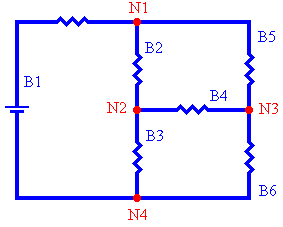
In this diagram we define:
- principal nodes or junctions - These are
points where 3 or more wires meet. This circuit contains 4 of
them, denoted N1, ..., N4. Notice the
 symbol for a principal node.
- branches - A branch is any path in the circuit that has a node at each end and contains at least one voltage source or resistor but contains no other nodes. This circuit contains 6 branches, denoted B1, ..., B6.
(Note: If branch B4 did not contain a resistor then it could be deleted and nodes N2 and N3 could be considered one and the same node.)
Electric Current
Electric charge flowing in a branch in a circuit is analogous to water flowing in a pipe. The rate of flow of charge is called the current. It is measured in coulombs/second or amperes (abbreviation A) just as the flow rate of water is measured in litres/second.
Water is incompressible, which means that if 1 litre of water enters one end of a length of pipe then 1 litre must exit from the other end. The situation is the same with electric current. If the current is 1A at a certain point in a branch then it is 1A everywhere else in that branch.
Kirchoff’s Current Law
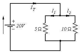
An immediate consequence of this is Kirchoff’s Current Law. Kirchoff’s current law states that the sum of the currents flowing into a node equals the sum of the currents flowing out of the node. Here is an example:
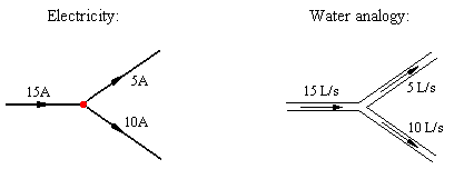
This diagram also shows how we draw an arrow on the branch to indicate the current flowing in the branch.
Electric Voltage
Electric current is the flow of electric charges. Electric voltage is the force that causes this flow. Just as a pump pushes a "plug" of water through a pipe by creating a pressure difference between its ends, so a battery pushes charge through a resistor by creating a voltage difference between the two ends of the resistor. The picture shows the analogy:
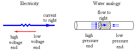
This diagram also shows how we draw an arrow beside a resistor or any other device to indicate a voltage difference between the two ends of that device. The arrow head is drawn pointing to the higher voltage end.
Ohm’s Law
We have just seen that a voltage difference between the two ends of a resistor causes a current to flow through the resistor. For many substances the voltage and current are proportional. This is expressed by the formula:
V = I R
This equation is called Ohm’s law and any device that obeys it is called a resistor.
V is the difference in voltage between the two ends of the resistor measured in volts, I is the current through the resistor measured in amperes, and the proportionality constant R is the resistance of the resistor measured in ohms. Given any two of these quantities, Ohm’s law can be used to find the third.
Kirchoff’s Voltage Law
Just as the water pressure drops in a garden hose the farther one moves away from the tap, so the voltage changes as one moves around a circuit away from a voltage source. Kirchoff’s Voltage Law states that:
Around any closed path in an electric circuit, the sum of the voltage rises through the voltage sources equals the sum of the voltage drops through the resistors.
A closed path is a path through a circuit that ends where it starts.
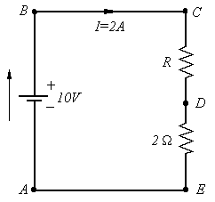
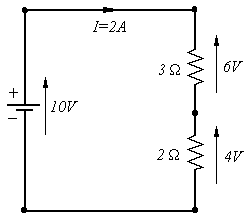
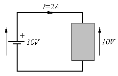
Problem: Resistors in Series. Use Kirchoff’s voltage law and Ohm’s law to find the value of the unknown resistor R if it is known that a 2 ampere current flows in the circuit.
